

The steps for installing a fixed ultrasonic flow meter are as follows:
First, set the pipe specifications, such as outer diameter, inner diameter, wall thickness, measured liquid, sensor type, installation method, etc. Finally, determine the installation distance and fix the sensor to the pipe according to the determined distance.
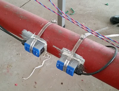

Quickly set measurement parameters and quickly master the installation method
I.Parameter settings:
1. Type MENU 1 1 to enter window 11, then press ENT to enter. Enter the pipe outer diameter and press ENT to confirm.
2. Type ▼/- to scroll down and enter window 12, then press ENT to enter. Enter the pipe wall thickness and press ENT to confirm.
3. Type ▼/- to scroll down and enter window 14, then press ENT to enter. Use the ▲/+ or ▼/- keys to select the pipe material and press ENT to confirm.
4. Type ▼/- to scroll down and enter window 16, then press ENT to enter. Use the ▲/+ or ▼/- keys to select the lining material and press ENT to confirm.
5. Type ▼/- to scroll down and enter window 20, then press ENT to enter. Use the ▲/+ or ▼/- keys to select the fluid type and press ENT to confirm.
6. Type ▼/- to scroll down and enter window 23, then press ENT to enter. Use the ▲/+ or ▼/- keys to select the sensor type and press ENT.
7. Type ▼/- to scroll down to window 24, then press ENT. Use the ▲/+ or ▼/- keys to select the installation method and press ENT to confirm.
8. Type ▼/- to scroll down to window 25. Install the sensor according to the displayed installation distance and the installation method selected in the previous step (see Sensor Installation).
9. Type MENU 2 6 to enter window 26, then press ENT. Use the ▲/+ or ▼/- keys to select "1. Solidify Parameters and Use All".
Then press ENT twice to confirm (this step is very important).
II. Selection and Positioning of Measurement and Installation Points:
1. Ideally, the pipe section should be straight, at least 10D from the upstream bend and 5D downstream (see instruction manual for details). If this is not possible, install the probe as close to the middle, slightly downstream. D is the outer diameter of the pipe.
2. If there is insulation on the pipe, remove part of the insulation layer according to the installation distance and method. After positioning, ensure that both sensors are on the same axial plane. The sensors must be installed on the side of the pipe, not on the top or bottom (as shown in the diagram).
III. Installation of External Clamp Sensors:
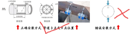
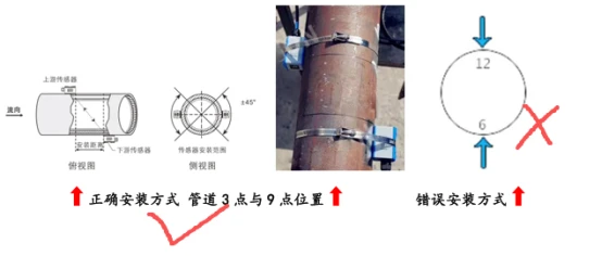
In actual measurements, considering the presence of air bubbles in the upper part of the pipe and sediment in the lower part, the 6 o'clock/12 o'clock positions should be avoided. The probe should be installed on both horizontal sides of the pipe. If space is limited, the probe can be installed vertically or at an angle, provided the pipe is full of liquid and free of air bubbles.
1: V-method installation applicable to pipe diameters ranging from DN32 to DN100. Schematic top/bottom view.
2: Z-method installation applicable to pipes larger than DN100. Schematic top/bottom view.
Ⅳ. Grinding the Installation Point:
Metal pipes need to be ground. Use an angle grinder or straight file to grind a square area approximately 1.5 times the area of the probe's bottom surface at the installation point to facilitate probe movement and optimal measurement signal adjustment. (PVC pipes do not need grinding; simply wipe them clean.) After grinding, the surface should be bright, smooth, and free of rust spots.
V. Probe Installation and Adjustment:
1. The ultrasonic flow meter has two probes, upstream and downstream.
First, evenly apply a 1-2 mm thick layer of coupling agent or silicone to the bottom surface of the upstream probe. Then, firmly attach the probe to the ground point on the upstream pipe and secure it with the provided steel strap (ensuring good coupling between the probe's bottom surface and the pipe surface, free of air bubbles, grit, or other impurities).
Ⅵ. Installation video for clamp-on Ultrasonic flow meters (TUF-2000B, TUF-2000M, TUF-2000S):